
Quick Answer
A septic tank plumbing diagram traces the complete underground path your household waste travels — starting at your home's drain pipes and ending in the soil beneath your yard. If you've ever stood in your yard wondering what's actually happening three feet below your feet, this is the map you need. About 21% of U.S. homes use a septic system rather than municipal sewer, according to EPA data. If yours is one of them, knowing what's underground can save you thousands of dollars — and help you recognize trouble before it turns into a $15,000 drain field replacement.
Key Takeaways
- A conventional gravity-fed septic system has 7–10 distinct components from your house to the end of the drain field.
- The house sewer line is typically 4-inch Schedule 40 PVC with a slope of 1/8 to 1/4 inch per foot.
- Wastewater separates into three layers inside the tank: scum, effluent, and sludge.
- A distribution box (D-box) splits effluent evenly between drain field trenches.
- Most gravity systems serve homes well for 25–40 years with proper maintenance — but the drain field is usually the first component to fail, typically after 15–25 years.
What Does a Septic Tank Plumbing Diagram Actually Show?
A septic tank plumbing diagram shows every component in your system's underground chain — from the main drain line leaving your house foundation all the way to the far end of your drain field laterals. Think of it as an X-ray of your yard. Each component appears in sequence: house sewer line, inlet baffle, tank compartments, outlet baffle, effluent filter, effluent pipe, distribution box, and perforated lateral pipes.
Reading one isn't complicated once you know what each symbol represents. Solid lines are pressure or solid pipes. Dashed lines typically indicate perforated pipes in the drain field. Rectangles represent tanks or boxes. The key detail most homeowners miss: the diagram always shows elevation changes, because gravity does most of the work. Every pipe has a specific slope, every transition has a reason. When something goes wrong — a soggy yard, a slow drain, a sewage smell — you can trace the problem backward through the diagram to narrow down the cause. That's the practical value of understanding the picture, not just knowing a system exists under your lawn.
How Does Plumbing Connect from a House to a Septic Tank?
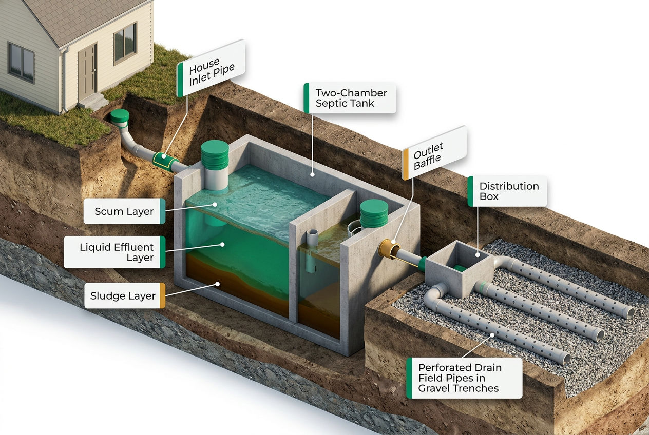
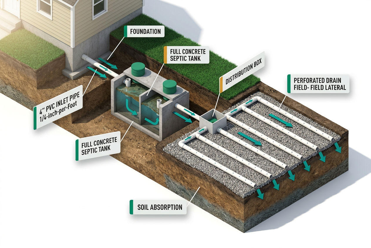
Your home's drain system funnels all waste — toilets, sinks, showers, washing machines — into a single main line called the house sewer line. This 4-inch Schedule 40 PVC pipe exits the foundation, typically 12–36 inches below grade, and runs downhill to the septic tank.
The critical detail here is slope. The pipe must drop between 1/8 inch and 1/4 inch per foot. Too shallow and solids settle and clog the line. Too steep and the liquid races ahead, leaving solids behind. A 30-foot run from your house to the tank should drop between 3.75 and 7.5 inches total — enough to maintain consistent flow without flushing liquid away from the waste. You can verify this yourself with a 4-foot level and tape measure if you have access to the pipe near the foundation.
Most jurisdictions require the tank to sit at least 5–10 feet from the house foundation, though 10 feet is the common minimum. The sewer line is buried deep enough to stay below your local frost line — 12–18 inches in the South, 42–60 inches in northern states like Minnesota or Maine. In northern climates, some contractors wrap the first 10 feet of pipe near the house with rigid foam insulation board to prevent a $1,500–$2,500 freeze-thaw service call.
For a closer look at how these components connect within the broader system, see our guide to what a septic system is and how it works.
What Does the Full House to Drain Field Diagram Look Like Underground?
Picture a chain of components buried in your yard, each one doing a specific job. Here's the full sequence in a standard gravity-fed septic system — what a complete house to drain field diagram maps out:
1. House drain network — all indoor drains flow to the main sewer line.
2. House sewer line — 4-inch Schedule 40 PVC, sloped 1/8–1/4 inch per foot, exits the foundation and runs to the tank.
3. Inlet baffle — inside the tank, this T-shaped fitting slows incoming flow so it doesn't disturb settled solids. It directs raw sewage downward into the liquid zone.
4. Septic tank — a watertight concrete, fiberglass, or polyethylene vessel. Modern code in most states requires two compartments. The first compartment handles primary settling; the second provides additional clarification before effluent exits.
5. Three internal zones — raw sewage separates naturally into a floating scum layer (fats, oils, grease), a middle liquid zone called effluent, and a settled sludge layer at the bottom. Only the middle effluent zone passes to the next stage.
6. Outlet baffle and effluent filter — the outlet baffle (also T-shaped) prevents scum from exiting with the effluent. Many modern tanks include a Polylok PL-122 effluent filter here, which catches suspended solids and protects the drain field from premature clogging.
7. Effluent pipe — a 4-inch PVC pipe carries clarified liquid from the tank outlet toward the drain field.
8. Distribution box (D-box) — a small concrete or plastic box that receives effluent from the tank and divides it equally among the drain field trenches. It's the traffic cop of your septic system.
9. Drain field laterals — perforated 4-inch PVC or HDPE pipes laid level in gravel-lined trenches. Effluent drips through the perforations, travels through gravel, and filters into the soil.
10. Soil absorption field — the native soil beneath the trenches provides the final treatment, removing pathogens and nutrients before the water reaches groundwater.
For detailed sizing and depth measurements across each component, our septic tank diagram with dimensions breaks it down visually.
Septic System Layout: Component Dimensions at a Glance
The table below summarizes typical specifications for each major component in a conventional gravity-fed septic system layout. Use these as benchmarks when reviewing your own inspection report or permit drawings — your local health department may require tighter tolerances.
| Component | Typical Specification | Notes |
|---|---|---|
| House sewer line | 4-in. Schedule 40 PVC | 1/8–1/4 in./ft slope |
| Tank depth below grade | 4–36 inches at lid | Varies by soil & frost zone |
| Tank capacity (3 BR) | 1,000–1,250 gallons | Size up for garbage disposal use |
| Drain field trench depth | 18–36 inches | Perforated pipe near top |
| Trench width × spacing | 1–3 ft wide; 6–10 ft centers | Per local perc test results |
Sources: EPA Onsite Wastewater Treatment Systems Manual; NOWRA Installation Standards; local health department minimums vary.
What Is a Distribution Box in a Septic System and Where Does It Go?
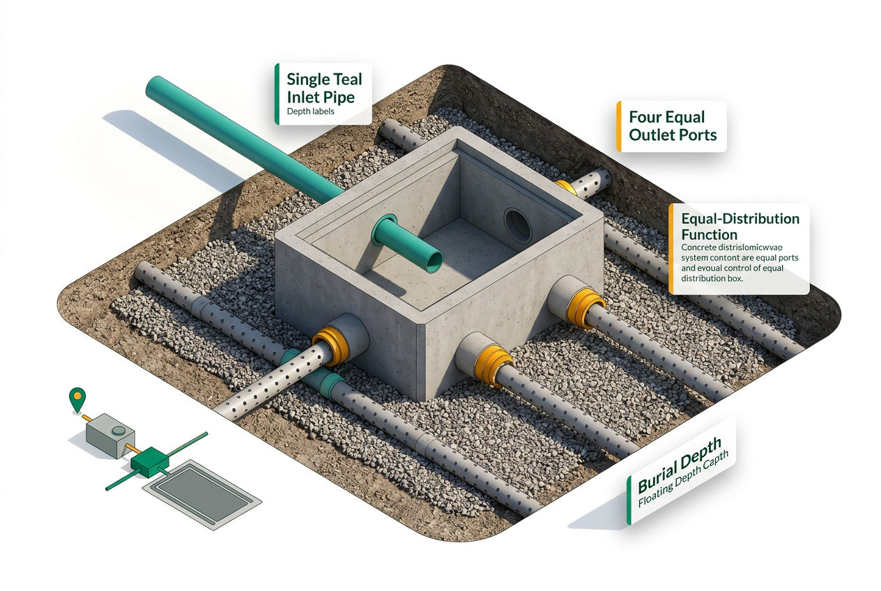
A distribution box, almost always called a D-box, sits between the septic tank outlet and the start of the drain field trenches. Its job is to split incoming effluent into equal flows so every lateral in the drain field receives the same volume. Without it, the closest trench would get overloaded while the far ones starve — and the overloaded trench fails years early.
D-boxes are typically precast concrete or heavy-duty plastic, set level in the ground (level matters enormously — a tilted D-box causes uneven distribution). They sit 5–20 feet from the tank, depending on site conditions, with a single inlet pipe on one side and multiple outlet pipes — one per lateral — on the other.
On older systems, D-boxes corrode or crack. A cracked D-box lets soil collapse into the distribution chamber, blocking outlets. If you notice one section of your yard perpetually soggy while another stays dry, a failed D-box is high on the suspect list. A septic inspection that includes camera inspection of the D-box can confirm this quickly.
What Is the Septic System Plumbing Diagram from Tank to Drain Field?
The effluent pipe leaving the tank outlet carries clarified liquid to the D-box, then the drain field lateral pipes branch out from there. This portion of the leach field piping diagram is where most homeowners get confused — so here's the exact layout:
- Effluent pipe (tank to D-box): 4-inch solid PVC, sloped slightly downhill. No perforations. This pipe should never allow soil intrusion.
- Distribution box connections: The D-box has one inlet and typically two to six outlets, each feeding a lateral.
- Lateral pipes (D-box to field ends): 4-inch perforated PVC or HDPE (Infiltrator Water Technologies makes widely used HDPE alternatives). These pipes are laid level, not sloped — you want effluent to distribute evenly along the full trench length, not pool at the downhill end.
- Trench bed: Perforated pipe rests on 6–12 inches of 3/4-inch crushed stone or engineered aggregate. Another 2 inches of stone covers the pipe before a geotextile fabric layer and backfill soil.
- Trench dimensions: 18–36 inches deep, 1–3 feet wide, spaced 6–10 feet on center. Length depends on your perc test results and local health department sizing charts.
For details on how trench layout affects system lifespan, read our drain field pipe types and layout guide.
How Far Should a Septic Tank Be from the House — and Everything Else?
Setback distances protect your drinking water, your neighbors' property, and your own foundation. These minimums are regulatory floors, not recommendations — your county health department may require more.
Typical minimum setbacks:
- House foundation to septic tank: 5–10 feet (10 feet is most common)
- Septic tank to drain field: 5–20 feet
- Drain field to private well: 50–100 feet (100 feet is the federal EPA benchmark)
- Septic tank to property line: 5–10 feet
- Drain field to property line: 10 feet minimum in most states
- Drain field to surface water (streams, lakes): 50–100 feet, state-dependent
These numbers directly affect your septic system layout options on smaller lots. A 1/4-acre lot with a well, a house, and a property line constraint can make it surprisingly difficult to fit a compliant system — which is why many tight lots require engineered alternatives.
Gravity System vs. Pump System: When the Diagram Changes
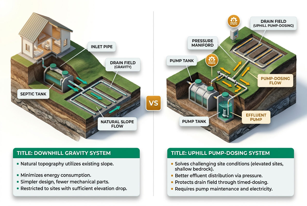
Most diagrams show a gravity-fed septic system because it's the most common setup in flat or gently sloping terrain with good native soil. But gravity doesn't always cooperate.
When your drain field sits uphill from your tank — or when native soil has poor percolation — you need a pump system. The septic system diagram with pump looks meaningfully different: a second tank or pump chamber sits between the septic tank and drain field, and a float-controlled pump delivers effluent in timed doses rather than continuous gravity flow.
Key components added in a pump system:
- Pump chamber (dosing tank): Holds effluent until the pump activates on a timer or float switch.
- Effluent pump: Submersible pump sized to the system — a Hiblow HP-80 linear air compressor is common in aerobic treatment units (ATUs); standard dosing systems use a Myers or Goulds submersible pump.
- Pressure manifold and lateral network: Instead of gravity-fed perforated pipe, pressurized systems use small-diameter PVC with precisely drilled orifices that distribute effluent evenly under pressure.
- Alarm float: Triggers an audible and visual alarm if the pump fails and the chamber reaches a critical level.
Pump systems cost more to install and require annual electrical and mechanical checks, but they allow placement on lots where gravity systems simply cannot work. For alternative configurations, see our guides on mound septic systems and alternative septic systems.
What Warning Signs Mean Something in the Diagram Has Failed?
Free download
Free: the Septic Fridge Card — what to flush, what never to.
The Do / Don’t card the whole family can see, plus the Survival Kit: emergency flowchart, warning-sign decoder and pump-schedule card. One printable PDF.
Each failure mode maps back to a specific component in the septic system plumbing diagram. Knowing the connection helps you describe the problem accurately when you call a professional.
Soggy ground over one part of the drain field, dry over another: Distribution box failure. The D-box has shifted, cracked, or one outlet is blocked — flow is going to one trench and bypassing others.
Slow drains throughout the house (not just one fixture): The problem is at or before the tank — either a clogged inlet baffle, a full tank (sludge and scum within 12 inches of the outlet), or a partially blocked house sewer line.
Sewage odor outside near the tank lids: Lid seal failure, a cracked riser, or a failed inlet baffle allowing gases to escape upward rather than venting through the house roof stack.
Sewage backup into the lowest fixtures: The tank is full, the outlet baffle has failed and solids are escaping toward the drain field, or the effluent pipe between tank and D-box is blocked.
Lush, unusually green grass over the drain field: Not always a problem in dry months, but in wet conditions it indicates surfacing effluent — the soil absorption field is saturated and no longer treating effluent before it reaches the surface.
If you see any of these symptoms, don't pump the tank first and assume the problem is solved. Pumping relieves pressure temporarily but won't fix a failed baffle, a cracked D-box, or a biomat-clogged drain field. Start with a septic inspection that includes the full component chain.
How Many Pipes Go Into a Septic Tank?
A standard septic tank has two pipes: one inlet and one outlet. The inlet pipe carries raw sewage from the house sewer line into the tank. The outlet pipe carries clarified effluent out toward the distribution box and drain field.
Both pipes connect to baffles inside the tank — T-shaped fittings that control flow direction. The inlet baffle directs incoming waste downward to prevent disturbing the settled sludge layer. The outlet baffle draws only from the middle effluent zone, preventing floating scum from escaping toward the drain field.
On two-compartment tanks (now required by code in most states), a submerged opening or internal partition wall connects the first and second chambers — but this isn't a separate pipe. It's part of the tank structure. Some jurisdictions allow an access riser pipe over each compartment lid, but those are maintenance access points, not flow pipes.
When Should You Call a Professional vs. Handle It Yourself?
Some tasks on the diagram are straightforward homeowner maintenance. Others require licensed professionals — both for safety and legal compliance.
Homeowner-appropriate tasks:
- Locating the tank lid and D-box using a probe rod and the as-built drawing from your county health department
- Scheduling routine pumping every 3–5 years (shorter if you use a garbage disposal or have more than four residents)
- Cleaning an accessible effluent filter like the Polylok PL-122 or Zabel A1800 — these pull out from the outlet baffle and can be rinsed with a garden hose over the tank opening
- Keeping vehicles, trees, and deep-rooted shrubs away from the drain field footprint
Licensed professional required:
- Any tank, baffle, or D-box repair or replacement
- Drain field installation or expansion — in most states this requires a licensed septic contractor and a health department permit
- Pump installation, electrical connection, and alarm wiring in dosing systems
- Any work requiring opening the tank and entering the chamber (confined space hazard)
Licensing varies significantly by state. Florida requires a Registered Septic Tank Contractor (RSTC) licensed through the Florida Department of Health. North Carolina requires a Licensed On-Site Wastewater Contractor. Texas routes permits through county-level Authorized Agents. Check your state health department's website before assuming a general plumber is qualified to perform septic work — many are not licensed for it.
If you are in the routine-maintenance lane — pumping is on schedule and the system is functioning normally — and you want to do something useful between service visits, a monthly bacterial treatment is the one task squarely in homeowner territory. We recommend Septifix for that role: each tablet releases oxygen alongside 14 strains of aerobic bacteria (roughly 10 billion CFU) to help break down sludge and reduce odors at the source, and dosing is as simple as flushing one tablet down the toilet. At roughly $3–$4 per treatment and with a 60-day money-back guarantee, the barrier to trying it is low. That said, no additive replaces pumping — the EPA is clear that additives are not required for a properly functioning system, and Septifix is not a substitute for scheduled pump-outs. See also our Rid-X vs. Septifix comparison if you are weighing options.
For a full discussion of what's legal to DIY, see our DIY septic system guide. For professional installation costs, see our septic installation cost guide.
Related Rid-X & Septic Treatment Guides
- The Best Rid-X Alternatives
- The Best Septic Tank Smell Removers
- Septic Smell When It Rains? Why It Happens & How to Fix It
- Can You Use Rid-X in an RV Black Tank? What to Know First
- Is Rid-X Safe for Septic Tanks, Toilets & Pipes?
- How Often Should You Use Rid-X? Directions, Dosing & Timing
- What's Actually in Rid-X? Ingredients Explained
- Does Rid-X Unclog Drains or Toilets?
- Rid-X vs. Green Gobbler: Which Septic Treatment Wins?
- Green Gobbler Septic Treatment Review: Pods, Packets & Results
- Where to Buy SeptiFix
- Bio-Clean Septic Treatment Review: Does It Work?
- Cabin Obsession Septic Tank Treatment Review
- Camco Septic Tank Treatment Review
- Septic Tank Treatments at Walmart vs. Home Depot vs. Online
- Septic Smell Coming From Toilet? Causes & How to Fix It
- Septic Smell From Shower Drain? Causes & How to Fix It
- Septic Tank Smell After Pumping? Causes & How to Fix It
- Septic Smell From Roof Vent? Causes & How to Fix It
- Is Septic Tank Smell Dangerous? Gases, Risks & When to Worry
- Septic Tank Diagram With Dimensions
- Septic Tank Cross-Section Diagram: Every Part Labeled
- Septic System Diagram With a Pump
- Aerobic Septic System Diagram: How Each Part Works
- Are Septic Tank Treatments Necessary?
- How to Handle How Often to Use Septic Tank Treatment: Step by Step
- Septic Treatment Tablets vs. Powder vs. Liquid: Which Is Best?
- Best Septic Tank Treatment for Slow Drains
- Yeast, Baking Soda & Milk in Your Septic Tank: Myths Tested
Frequently Asked Questions
What does a septic system plumbing diagram show?
A septic system plumbing diagram shows every underground component your wastewater passes through, in order, from the house drain network to the far end of the drain field. Specifically, it maps the house sewer line exiting your foundation, the inlet baffle inside the tank, the tank's two compartments, the outlet baffle and effluent filter, the effluent pipe running to the distribution box, and the perforated lateral pipes spreading through the drain field trenches. Each component appears with its approximate depth, pipe size, and slope. Elevation changes are always shown because gravity drives flow through the entire system. Reading the diagram gives you a way to trace any symptom — a soggy yard, a slow drain, a sewage odor — back to its likely source in the chain. Most county health departments have a copy of your system's as-built drawing on file, which is the real-world version of this diagram for your specific property.
How do I read a septic system diagram?
Start at the house and follow the flow. The house sewer line is always the first element — a solid line exiting the foundation at an angle indicating downward slope. Follow it to the tank rectangle, which is usually labeled with its gallon capacity. Inside the tank, look for two vertical lines near the inlet and outlet — those are the baffles. The outlet side connects to another solid line (the effluent pipe) running to a small square or circle labeled "D-box" or "distribution box." From the D-box, multiple dashed lines branch out — those are the perforated lateral pipes in the drain field. Dashed lines mean perforated; solid lines mean non-perforated. Depth notations appear as numbers beside each component. If you see a second tank or a pump symbol between the septic tank and D-box, you have a pump-dosed system. Your county health department's as-built drawing uses this same convention and applies it to your actual lot dimensions and soil conditions.
What size pipe is used in a septic system?
The standard pipe size throughout a conventional septic system is 4-inch diameter. This applies to the house sewer line leaving your foundation, the inlet and outlet connections at the tank, the effluent pipe running from the tank to the distribution box, and the perforated lateral pipes in the drain field. The house sewer line is 4-inch Schedule 40 PVC — a thicker-walled pipe rated for burial and occasional ground movement. The lateral pipes in the drain field are also 4-inch diameter but perforated, available in either PVC or HDPE. Infiltrator Water Technologies HDPE chambers are a common alternative to traditional perforated pipe in modern installations. The only exception to the 4-inch standard appears in pressurized pump systems, where small-diameter pressure-dosed laterals (typically 1.25–2 inch) replace the gravity-fed perforated pipe, using precision-drilled orifices to distribute effluent evenly across the field.
How deep are septic system pipes buried?
Depth varies by component and by your local frost line. The house sewer line exits the foundation anywhere from 12 to 36 inches below grade, depending on how deep the house drain exits and the local frost depth — 12–18 inches in southern states, 42–60 inches in northern states like Minnesota or Maine. The septic tank lid sits 4–36 inches below grade depending on site grading and the installer's design. Effluent pipe between the tank and distribution box is typically buried at the same depth as the tank outlet — usually 12–24 inches. Drain field lateral pipes sit 18–36 inches deep, resting on 6–12 inches of crushed stone with the perforated pipe near the top of the stone bed. In cold climates, shallower components near the house may be insulated with rigid foam board. If you're trying to locate buried components, a soil probe rod and the as-built drawing from your county health department are the most reliable starting points.
What is a septic distribution box diagram?
A septic distribution box diagram shows the D-box as a small square or rectangular box positioned between the tank outlet and the start of the drain field. One inlet pipe enters from the tank side, and multiple outlet pipes — typically two to six — exit toward individual drain field laterals. The diagram always shows the D-box sitting level, because a tilted D-box is the single most common cause of uneven drain field loading. In a proper septic distribution box diagram, all outlet pipe inverts (the bottom of each pipe opening inside the box) sit at exactly the same elevation. If one outlet is lower than the others, all flow goes to that trench. The D-box appears on your system's as-built drawing with its distance from the tank noted — usually 5–20 feet. If you're troubleshooting uneven drain field saturation (one wet section, one dry section), the D-box is the first place a licensed inspector will look.
How long does a septic drain field last?
A properly designed and maintained drain field typically lasts 15–25 years, though some systems in ideal soil conditions run 30–40 years. The drain field is almost always the first major component to fail in a septic system — the tank itself can last 40+ years with concrete construction. Failure happens when the biomat — a layer of organic material and bacteria — builds up at the soil interface beneath the trench, eventually blocking water movement into the native soil. Premature failure accelerates when the tank is never pumped (solids escape and clog the field), when a failed effluent filter lets suspended solids through, or when hydraulic overload saturates the soil faster than it can recover. You can extend field life by pumping your tank on schedule (every 3–5 years for a 1,000-gallon tank serving four people), repairing baffles and effluent filters promptly, and keeping the field free of vehicle traffic and deep-rooted plants. For replacement cost planning, see our drain field replacement cost guide.
Sources & Methodology
- U.S. Environmental Protection Agency. Onsite Wastewater Treatment Systems Manual (EPA/625/R-00/008). Primary reference for system component sizing, setback distances, and soil absorption field design criteria.
- National Onsite Wastewater Recycling Association (NOWRA). Installation and maintenance standards used for pipe sizing and trench specification benchmarks.
- National Association of Wastewater Technicians (NAWT). Inspection and pumping frequency guidance referenced for maintenance intervals.
- Florida Department of Health. Registered Septic Tank Contractor (RSTC) licensing requirements.
- North Carolina On-Site Water Protection Branch. Licensed On-Site Wastewater Contractor credential requirements.
- Texas Commission on Environmental Quality (TCEQ). County-level Authorized Agent program for on-site sewage facility permits.
- Polylok, Inc. Product specifications for PL-122 effluent filter.
- Infiltrator Water Technologies. HDPE chamber and pipe product documentation.
- Zabel Environmental Technology. A1800 series effluent filter specifications.
Cost ranges and installation specifications reflect contractor interviews and permit data reviewed through the date of publication. Local requirements vary — always verify with your county health department before beginning any septic work.
Was this article helpful?
Frequently Asked Questions
Recommended Resources
📖 Related Articles
- What Is a Septic System? How It Works (Visual Guide)
- Septic Tank Diagram With Dimensions (Sizes, Depths & Layout)
- What Is a Distribution Box in a Septic System?
- Septic System Design: Layouts, Drawings & Requirements
- Septic System Diagram With a Pump (How Pumped Systems Work)
- Mound Septic System: $10K–$25K Cost & How It Works (2026)
- Alternative Septic Systems: Options When a Standard System Won't Work
- DIY Septic System: How to Build Your Own (Step-by-Step)
💰 Cost Guides
🔧 Services
Find Septic Professionals Near You
Compare licensed, verified septic companies by area — top county markets and cities below, or browse all 50 states.
County markets
Popular cities
