

See a labeled septic system diagram with every component explained. Learn how the tank, baffles, distribution box, and drain field work together step by step.
Quick Answer
National ranges are a starting point. Get 3 free quotes from licensed local septic pros priced for your soil, lot size, and county requirements.
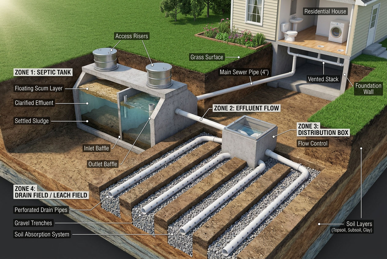
A septic system diagram shows the complete path wastewater takes from your house through the underground treatment system and back into the soil. The four main zones are the sewer line, the septic tank, the distribution box, and the drain field — each with specific components that must function properly for the system to protect your home and groundwater.
Key Takeaways
- A septic system has 4 main zones: sewer line, tank, distribution box, and drain field
- The septic tank separates waste into 3 layers: scum (top), effluent (middle), sludge (bottom)
- Baffles at the inlet and outlet are critical — they keep solids from reaching the drain field
- The drain field does the final treatment — soil bacteria remove up to 99% of harmful pathogens
- A typical residential system occupies 1,500-3,000 sq ft of yard space
Whether you're a new septic homeowner trying to understand your system, a buyer getting a home inspection, or just curious about what's buried in your backyard, a labeled diagram is the fastest way to make sense of how everything connects. Most homeowners interact with their septic system only when something goes wrong — understanding the components now helps you recognize problems early and maintain the system properly.
This guide walks through every labeled component of a conventional septic system, explains what each part does, and shows how they work together.
Find a licensed septic professional in your area on SepticTankHub.com
A labeled diagram of a septic system shows four main zones — sewer line, septic tank, distribution box, and drain field — connected by gravity-fed pipes that move wastewater from the house through underground treatment and back into the soil. This section walks through every component on a standard residential septic system diagram, with cross-section views and component-by-component explanations of how each part works.
The anatomy of a septic system is consistent across most U.S. installations: a 4-inch sewer line exits the house foundation, slopes downward into a buried watertight tank where solids settle, then routes clarified effluent through a distribution box into perforated drain field laterals where soil microbes complete the treatment. Understanding this anatomy is the foundation for everything else — diagnosing problems, planning maintenance, and meeting setback requirements.
A conventional septic system is entirely underground and invisible from the surface. Here's what the complete system looks like in cross-section, from house to soil:
Zone 1 — House to Tank (the sewer line). A 4-inch PVC or cast iron pipe carries all wastewater from your home to the septic tank. This pipe exits through the foundation wall and slopes downward at a grade of 1/8 to 1/4 inch per foot. Gravity does all the work — no pumps needed in this section. The pipe typically runs 10-25 feet from the house foundation to the tank inlet.
Zone 2 — The septic tank. A watertight concrete, fiberglass, or plastic container buried 1-4 feet below ground. Standard residential tanks hold 1,000-1,500 gallons. Inside, wastewater separates into three layers through natural settling. The tank is where 60-80% of solids removal happens.
Zone 3 — Distribution system. A distribution box (D-box) or drop box receives clarified effluent from the tank outlet and divides it equally among the drain field trenches. This ensures even distribution so no single trench gets overloaded.
Zone 4 — The drain field. A network of perforated pipes laid in gravel-filled trenches 18-36 inches below the surface. Effluent seeps through the pipe perforations into the gravel and surrounding soil, where bacteria complete the treatment process. The drain field is the largest component, covering 500-2,000+ square feet depending on soil type and household size.
| Component | Typical Size | Depth Below Ground | Material |
|---|---|---|---|
| Sewer line | 4" diameter, 10-25 ft long | 2-4 feet | PVC or cast iron |
| Septic tank | 5' × 8' × 5' (1,000 gal) | 1-4 feet to lid | Concrete, plastic, or fiberglass |
| Distribution box | 2' × 2' × 1.5' | 1-3 feet | Concrete or plastic |
| Drain field pipes | 4" diameter, 50-100 ft each | 18-36 inches | Perforated PVC |
| Drain field trenches | 1-3 ft wide × 50-100 ft long | 18-36 inches | Gravel bed + soil |
Source: EPA septic system design standards and International Private Sewage Disposal Code
Key Insight: The drain field is often the most expensive component to replace — $5,000-$20,000 — yet it's the part most homeowners know least about. Everything upstream (the tank, baffles, and sewer line) exists to protect the drain field from damage. When any upstream component fails, the drain field pays the price.
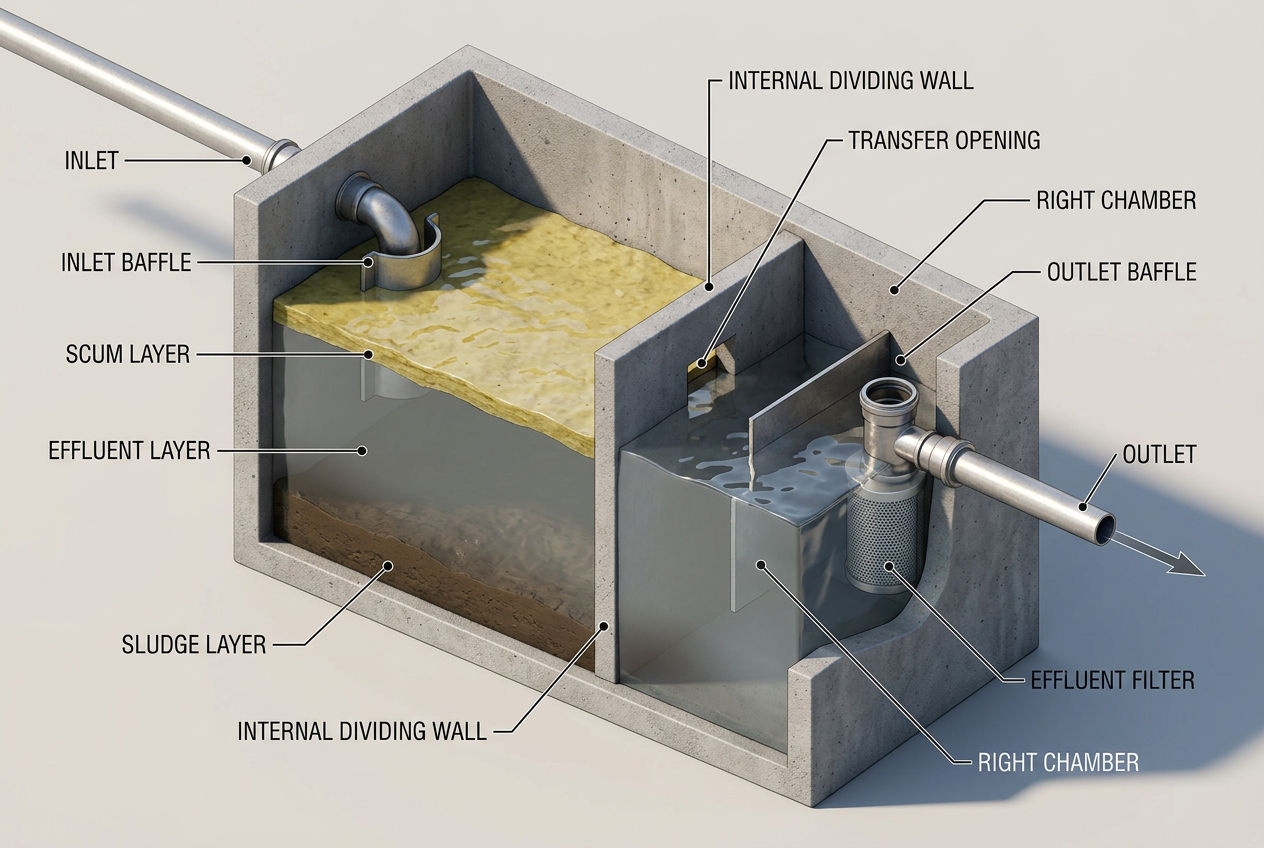
The components of a septic tank are: inlet baffle, scum layer, effluent zone, sludge layer, outlet baffle, effluent filter, and (in modern tanks) a dividing wall creating two chambers. A diagram of a septic tank with baffles labeled shows exactly where each part sits and why each one matters — the tank is the heart of the system, and understanding its anatomy explains why regular pumping (typically $400–$750 every 3–5 years) is non-negotiable.
Inlet baffle. Located where the sewer pipe enters the tank. The baffle directs incoming wastewater downward into the liquid zone, preventing it from disturbing the settled sludge layer or the floating scum. Without a functioning inlet baffle, incoming waste creates turbulence that pushes solids toward the outlet. A damaged inlet baffle is one of the most common baffle repair needs.
Scum layer (top). Grease, oils, soap residue, and other materials lighter than water float to the surface and form a thick mat. In a healthy tank, this layer is 3-6 inches thick. The scum traps gases produced by anaerobic decomposition below.
Effluent zone (middle). The clarified liquid between the scum and sludge layers. This is the only material that should leave the tank — everything else stays behind. In a properly maintained tank, the effluent zone occupies about two-thirds of the total volume.
Sludge layer (bottom). Heavy solids that settle through the liquid — food particles, human waste, soil, and inorganic material. Anaerobic bacteria break down some of this sludge, but the inorganic portion accumulates permanently. This is what gets removed during pumping.
Outlet baffle. The most critical protective component. The outlet baffle extends below the liquid surface (typically 12-18 inches) to draw effluent from the clear zone while blocking scum and floating solids from reaching the drain field. A missing or broken outlet baffle is the number one cause of premature drain field failure.
Effluent filter. A cylindrical filter installed in or near the outlet baffle that catches fine suspended solids the baffle alone would miss. Modern codes in most states require effluent filters on new installations. The filter needs cleaning every 1-2 years — see our effluent filter guide for maintenance details.
Dividing wall (two-compartment tanks). Most modern tanks have an internal wall creating two chambers. Wastewater enters the larger first chamber (about 2/3 of total volume) where primary settling occurs. A transfer opening lets liquid flow into the smaller second chamber for additional settling before reaching the outlet. This dual-chamber design produces cleaner effluent.
Pro Tip: When your tank is pumped, ask the technician to check both baffles visually while the tank is empty. A 5-minute baffle inspection during pumping catches damage early — before solids escape to the drain field. Baffle replacement costs $200-$400 at the time of pumping, versus thousands in drain field repair if caught too late.

DIY Septic Blueprint
The complete, plain-English plan to size, permit and install your own septic system — designed for homeowners, not contractors. Skip the $15,000–$25,000 quotes and do it right the first time.
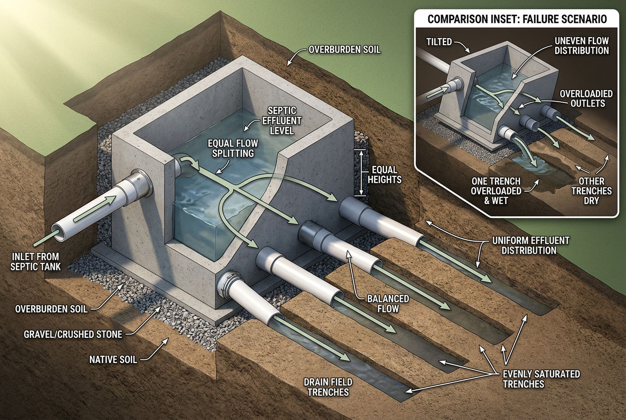
Get the DIY Blueprint — $67 →Instant download · 8 modules + 3 bonus guides · 60-day money-back guaranteeThe distribution box (D-box) is a small concrete or plastic box that sits between the septic tank outlet and the drain field. Its job is simple but critical: split the effluent flow equally among all drain field trenches.
A typical D-box has one inlet and 3-6 outlets, each feeding a separate trench. The outlets are set at the same level so effluent divides evenly. If the D-box settles, cracks, or shifts — which happens over time due to soil movement, frost heaving, or root intrusion — some trenches receive more flow than others. Overloaded trenches fail faster, while underloaded trenches dry out and lose their biological treatment capacity.
Signs of a failing distribution box include uneven wet spots in the drain field area (one section soggy while others are dry), one trench showing surface effluent while others look fine, or persistent odors localized to one area of the drain field.
D-box leveling or replacement costs $500-$1,500 — far less than replacing the drain field trenches that fail from uneven loading.
Common Mistake: Ignoring the distribution box during routine inspections. Most homeowners and even some septic companies focus only on the tank and drain field. A D-box that's shifted just 1-2 degrees can send 60-70% of effluent to a single trench instead of distributing it equally across four. Ask your inspector to check D-box levelness during every full system evaluation.
The drain field (also called a leach field or absorption field) is where the final treatment happens. It's not just a disposal area — it's an engineered biological treatment system.
Perforated distribution pipes run through gravel-filled trenches. Effluent exits through small holes in the pipes (typically 1/2 inch diameter, spaced every 6-12 inches) and seeps into the surrounding gravel.
Gravel bed (12-36 inches of washed stone) creates air space around the pipes. This aeration supports aerobic bacteria that break down remaining organic matter the tank didn't remove. The gravel also distributes effluent across the full length of each trench.
Biomat layer — a critical biological film that forms at the gravel-soil interface. This living layer of bacteria is where 90-99% of pathogen removal occurs. The biomat regulates how fast effluent enters the native soil, preventing too-rapid percolation that would contaminate groundwater. A healthy biomat is essential — without it, untreated effluent reaches groundwater too quickly.
Native soil below the biomat provides the final filtration. Sand and clay particles physically filter remaining bacteria and viruses. Soil bacteria continue breaking down organic compounds. By the time water reaches the groundwater table — typically 2-4 feet below the drain field pipes — it's been treated to near-drinking-water quality.
Drain field trenches are installed at specific depths based on soil type, percolation rate, and local codes. Proper depth ensures adequate treatment time in the soil column above the water table.
| Soil Type | Perc Rate (min/inch) | Required Trench Length per Bedroom | Suitability |
|---|---|---|---|
| Sand/gravel | 1-5 | 50-75 ft | Excellent (may need design limits) |
| Sandy loam | 6-15 | 75-100 ft | Good |
| Loam | 16-30 | 100-150 ft | Acceptable |
| Clay loam | 31-60 | 150-200+ ft | Marginal (may need alternative) |
| Heavy clay | 60+ | Not suitable | Alternative system required |
Source: EPA Design Manual for Onsite Wastewater Treatment Systems
Key Insight: Soil type determines drain field size more than any other factor. A home on sandy soil might need 200 feet of total trench length, while the same home on clay loam could need 600+ feet — or an alternative system entirely. This is why the percolation test done before installation is so important.

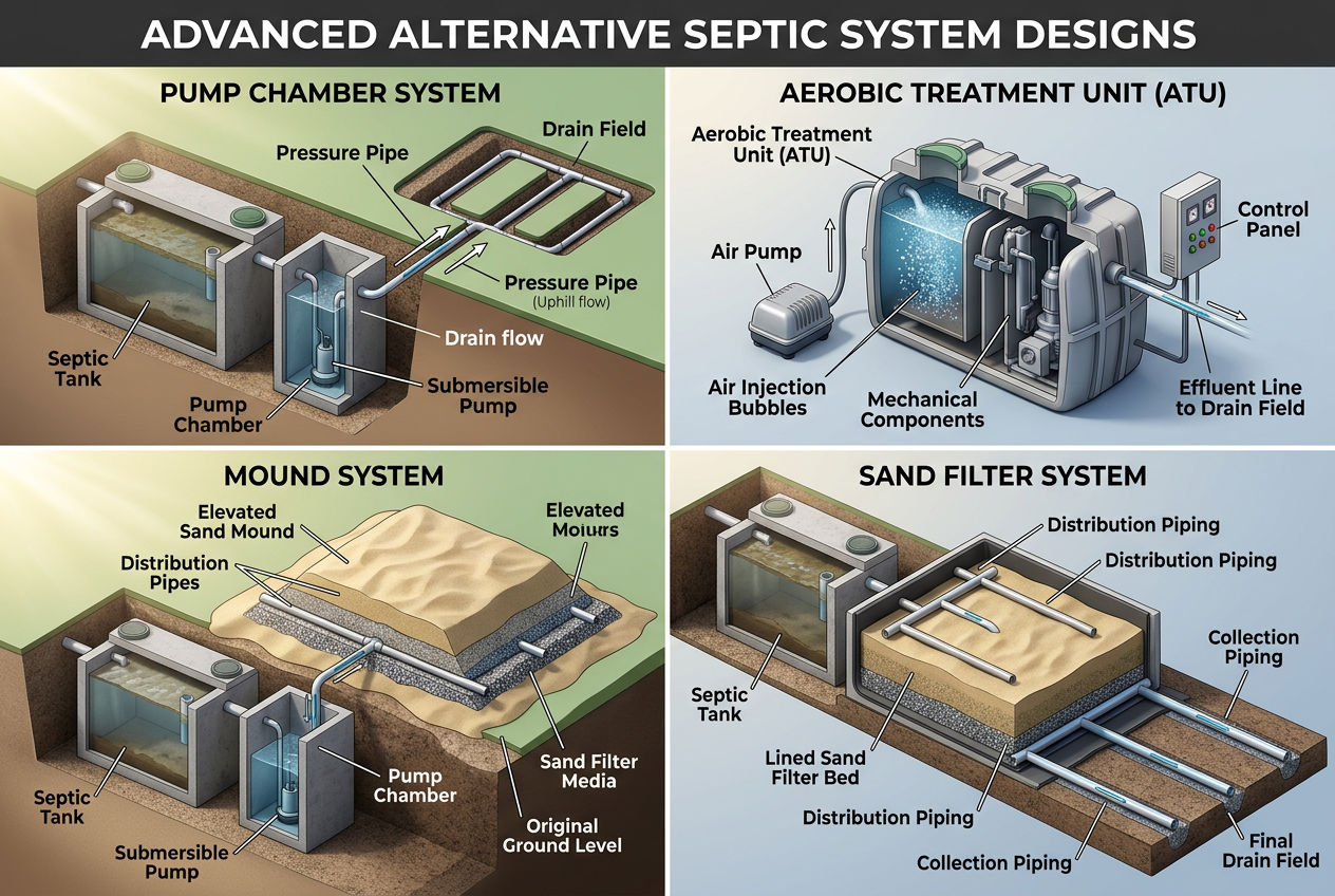
Not every property can support a conventional gravity-fed system. When soil, terrain, or space constraints prevent a standard design, alternative systems add components to compensate:
Pump chamber systems add an additional tank with a submersible pump between the septic tank and the drain field. The pump doses the drain field in timed intervals rather than continuous gravity flow. This allows the drain field to rest between doses, extending its life. Required when the drain field is uphill from the tank.
Aerobic treatment units (ATUs) replace or supplement the conventional tank with an oxygen-injected chamber. Aerobic bacteria break down waste 20-30 times faster than the anaerobic bacteria in a standard tank, producing much cleaner effluent. ATUs are required when soil conditions limit drain field capacity.
Mound systems build an elevated drain field above the natural ground surface using sand fill. Used when the water table is too high or bedrock too shallow for conventional trenches. The mound provides additional treatment depth that the natural soil can't.
Sand filter systems route effluent through a lined bed of engineered sand before it reaches the drain field. The sand provides consistent treatment quality regardless of native soil conditions. Common in coastal areas and near sensitive water bodies.
Each alternative design adds $5,000-$20,000 to the installation cost compared to a conventional system. They also require ongoing maintenance — typically $200-$500/year for ATUs — that conventional systems don't. Which layout your county approves comes down to septic system design requirements — soil test results, setback distances, and calculated daily flow.
Understanding your system's layout helps you maintain it correctly and avoid costly mistakes:
Know your setbacks. Every component has required distances from wells, property lines, buildings, and water features. Violating setbacks can contaminate water sources. Our setback requirements guide lists the standard distances.
Protect the drain field. Never drive vehicles over it, build structures on it, or plant trees within 30 feet. Roots clog pipes and heavy loads compress the gravel and soil that enable treatment.
Monitor each zone. During routine maintenance, a thorough inspection checks every labeled component: sewer line condition, tank integrity, baffle function, effluent filter cleanliness, D-box levelness, and drain field absorption.
Map your system. Sketch the labeled diagram with your specific measurements — distance from house to tank, tank to D-box, D-box to drain field trenches. Share this with your service company. It saves time and money on every visit.
EPA — Design Manual for Onsite Wastewater Treatment Systems — Federal design standards including component specifications, soil requirements, and sizing tables
EPA — Types of Septic Systems — Descriptions of conventional and alternative system configurations with component diagrams
University of Minnesota Extension — How Your Septic System Works — Research-based explanations of wastewater treatment processes in each system component
International Code Council — International Private Sewage Disposal Code — Model code establishing component specifications, setback distances, and design requirements
SepticTankHub.com Internal Data — System type distribution and component data compiled from 4,200+ listed septic service companies
Was this article helpful?
Connect with licensed, verified septic companies in your area.
Get estimates from licensed, verified companies in your area. No obligation.
⚡ Average response time: under 2 hours