

Drain field pipe is 4-inch perforated PVC installed in gravel trenches. Learn pipe specs, layout patterns (serial, parallel, pressure-dosed), and spacing rules.
Quick Answer
National ranges are a starting point. Get 3 free quotes from licensed local septic pros priced for your soil, lot size, and county requirements.
Drain field pipe is the perforated pipe buried in gravel-filled trenches that distributes treated septic effluent into the surrounding soil for final treatment. Standard residential systems use 4-inch perforated PVC with 1/2-inch holes, installed across 3-6 parallel trenches totaling 200-600 linear feet. How the pipe is arranged — the layout pattern — determines how evenly effluent spreads across the absorption area, which directly affects how long the field lasts and how well it performs.
Key Takeaways
- Standard drain field pipe is 4-inch perforated PVC with 1/2-inch holes every 6-12 inches
- Three layout patterns: parallel (most common), serial (sloped sites), pressure-dosed (challenging soils)
- Typical 3-bedroom home uses 200-600 linear feet across 3-6 trenches
- Pipe slope must be 1/8 to 1/4 inch per foot — too much slope sends all effluent to the far end
- Layout design is based on your perc test results and lot topography
When homeowners think about their drain field, they usually picture the trenches. But the pipe inside those trenches is what makes the system work — it controls where effluent goes, how evenly it's distributed, and whether the full absorption area gets used or just a fraction of it. Poor pipe layout is one of the most common reasons drain fields underperform, even in good soil.
This guide covers the pipe itself (materials, specifications, perforation patterns), the three main layout configurations, and the spacing and slope rules that determine how your system performs.
For a comparison of pipe types by cost and performance, see our septic field lines guide. For gravelless alternatives that eliminate the need for gravel aggregate, see our gravelless leach field pipe guide.
Find a licensed septic installer in your area on SepticTankHub.com
Drain field pipe serves one function: distributing effluent evenly across the trench bottom so the soil can absorb and treat it. The pipe doesn't filter or treat the wastewater — that's the soil's job. The pipe is just the delivery system.
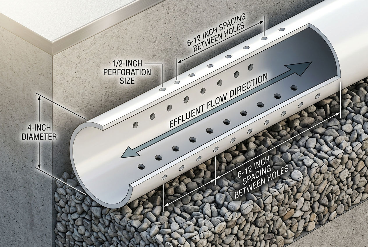
The default drain field pipe in most U.S. installations is 4-inch diameter Schedule 40 PVC with two rows of 1/2-inch perforations drilled along the bottom half. The holes face downward into the gravel bed when installed, allowing effluent to seep out evenly along the full length of each trench.
| Specification | Standard Value |
|---|---|
| Material | PVC (Schedule 40) or HDPE |
| Diameter | 4 inches |
| Perforation size | 1/2 inch |
| Perforation spacing | 6-12 inches (varies by manufacturer) |
| Perforation location | Bottom half of pipe (two rows) |
| Installation slope | 1/8 to 1/4 inch per foot |
| Available lengths | 10-foot sections (PVC) or continuous rolls (HDPE) |
Source: International Private Sewage Disposal Code design standards
High-density polyethylene pipe is lighter and more flexible than rigid PVC. It comes in continuous rolls rather than 10-foot sections, which reduces the number of joints and makes installation faster on curved or irregular trench layouts. The trade-off is that the corrugated wall profile can trap more sediment than smooth-wall PVC over time.
Not all pipe in a drain field system is perforated. The solid pipe sections are just as important:
Tank to distribution box: 4-inch solid PVC or HDPE connects the septic tank outlet to the distribution box. This pipe carries effluent without releasing any into the soil — it's a sealed transport line.
Distribution box to trench headers: Solid pipe from the D-box to the beginning of each trench ensures effluent reaches the trenches before any is released.
Perforated pipe starts only once the pipe enters the gravel-filled trench where absorption is designed to occur.
Key Insight: The transition point from solid to perforated pipe is critical. If the perforated section starts before the gravel bed begins, effluent leaks into untreated soil near the distribution box — concentrating flow in one area and starving the rest of the field. During installation, this joint should be inspected before backfill.
How drain field pipe is arranged across the yard matters as much as the pipe material itself. The layout pattern determines whether effluent reaches the entire absorption area evenly or concentrates in a fraction of the available soil.
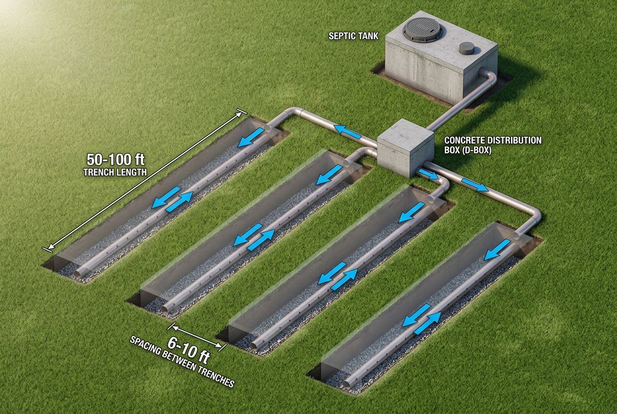
The most common residential drain field layout. A distribution box receives effluent from the tank and splits it equally among 3-6 parallel trenches. All trenches receive flow simultaneously, and each trench handles an equal share of the total volume.
How it works: The D-box sits at the uphill end of the field. Equal-diameter pipes run from the D-box to each trench. Because the D-box outlets are at the same elevation, gravity distributes flow evenly. Each trench operates independently — if one is slightly more absorbent, it takes a bit more flow, but the difference is minimal when the D-box is properly leveled.
Best for: Flat or gently sloping sites where all trenches can be installed at approximately the same elevation. This is the default layout for most residential systems.
Trench specifications:
| Parameter | Typical Range |
|---|---|
| Trench length | 50-100 feet |
| Trench width | 1-3 feet |
| Trench spacing (center to center) | 6-10 feet |
| Number of trenches | 3-6 |
| Minimum undisturbed soil between trenches | 4-6 feet |
| Total linear feet (3-BR home) | 200-600 feet |
Source: International Residential Code and state health department design standards
Pro Tip: The spacing between trenches isn't arbitrary — it ensures enough undisturbed soil between trenches to maintain structural integrity and prevent adjacent trenches from saturating each other. Never let a contractor reduce trench spacing below code minimum to fit a field into a smaller area. If the field doesn't fit, the site may need an alternative system design.
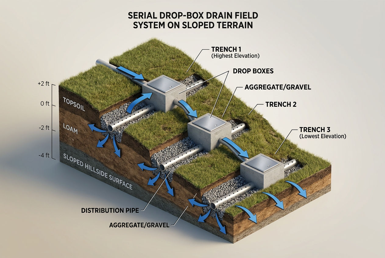
Used on sloped sites where trenches must step down the hillside at different elevations. Instead of a single distribution box feeding all trenches simultaneously, a series of drop boxes connects the trenches in sequence. Effluent fills the first (highest) trench, and when it reaches capacity, it overflows through the drop box into the next trench downhill.
How it works: Each drop box has an outlet at a set height. Effluent fills the upstream trench until it reaches the overflow level, then passes to the next trench. This means the first trench handles the most volume and the last trench handles the least — the load is distributed unevenly by design.
Best for: Sites with 5%+ slope where parallel trenches at the same elevation aren't feasible. The trenches step down the hill following the natural grade, with each trench cut into the slope at its own level.
Key difference from parallel: In a parallel system, all trenches share the load evenly. In a serial system, the first trench gets the heaviest use and will age faster. Some installers rotate which trench receives flow first by installing diverter valves in the drop boxes, extending the overall field life.
Common Mistake: Installing a parallel distribution box on a sloped site. If the site has more than 2-3 feet of elevation change across the field area, a standard D-box can't distribute evenly — gravity sends most flow to the lowest outlet. Serial distribution with drop boxes is the correct solution for significant slopes.

DIY Septic Blueprint
The complete, plain-English plan to size, permit and install your own septic system — designed for homeowners, not contractors. Skip the $15,000–$25,000 quotes and do it right the first time.
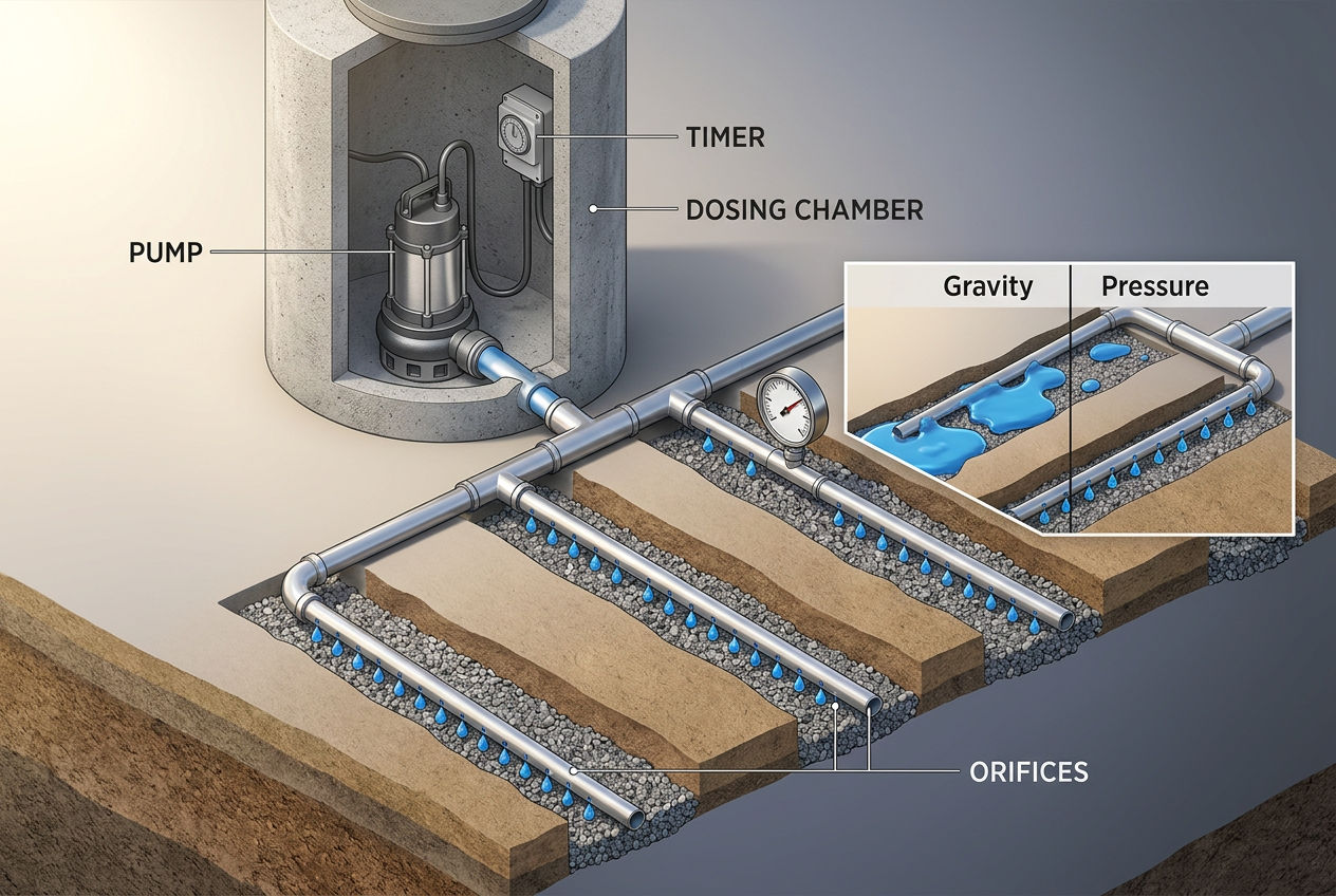
Get the DIY Blueprint — $67 →Instant download · 8 modules + 3 bonus guides · 60-day money-back guaranteeA pump and timer system that pressurizes the drain field pipe to force effluent out through small-diameter orifices (1/8 to 1/4 inch) simultaneously along the entire pipe network. Instead of gravity feeding effluent from one end, pressure dosing delivers equal amounts at every point in the field at the same time.
How it works: Effluent collects in a dosing chamber (pump tank) between the septic tank and the field. A pump activates on a timer or level switch, pushing a measured dose through the pressurized pipe network. The small orifices are calibrated so that pressure is equalized across the entire system — the first hole delivers the same amount as the last.
Best for: Challenging sites — shallow soil over bedrock, poor percolation rates, small lots requiring maximum use of available area, or any situation where perfectly even distribution is critical. Also required by some states for advanced treatment systems.
Cost premium: Pressure-dosed systems cost $2,000-$5,000 more than gravity systems due to the pump, dosing chamber, controls, and smaller-diameter pressurized pipe. They also require electricity and periodic pump maintenance. See our septic installation cost guide for full system cost breakdowns.
Key advantage: Pressure dosing is the most even distribution method available. Every square foot of the drain field receives the same volume of effluent, which means the soil is used to its maximum capacity. This allows smaller fields or fields in marginal soil to perform as well as larger gravity-fed fields in ideal soil.
Regardless of layout pattern, certain pipe installation rules apply to every drain field. Getting these wrong leads to uneven distribution, premature field failure, or code violations.
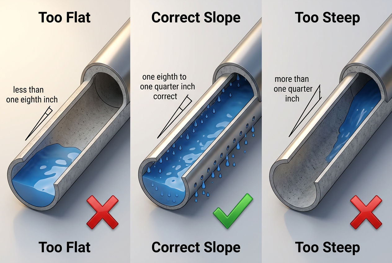
Drain field pipe must slope downhill at 1/8 to 1/4 inch per foot. This narrow range is critical:
Too little slope (less than 1/8 inch per foot): Effluent pools in low spots along the pipe instead of flowing to the far end. The near end of each trench gets overloaded while the far end sits unused.
Too much slope (more than 1/4 inch per foot): Effluent rushes to the far end of each trench before having time to seep through the upstream perforations. The far end gets overloaded while the near end dries out.
The correct slope ensures effluent moves slowly enough to seep out through every perforation along the full pipe length, loading the trench evenly from beginning to end.
Drain field pipe is typically buried 18-36 inches below grade, sitting on a 6-12 inch gravel bed within the trench. The pipe depth is governed by two competing requirements: deep enough for soil cover and freeze protection, but shallow enough to keep the effluent within the aerobic soil zone where biological treatment occurs.
Standard installations require 6-12 inches of 3/4 to 2-1/2 inch washed stone below the pipe and 2-4 inches above. The gravel provides structural support, void space for temporary storage, and a distribution surface. Gravelless alternatives replace the stone with engineered products that serve the same function.
Quick Fact: The gravel in a drain field trench provides approximately 30% void space — meaning 30% of the gravel bed volume is available for effluent storage during peak loading. Chamber systems provide about 40% void space, which is why they can use shorter trenches than conventional gravel-and-pipe systems.
Your septic designer or installer makes the layout recommendation based on three factors:
1. Site topography. Flat lots get parallel distribution. Sloped lots (5%+ grade) get serial drop-box distribution. Sites with irregular terrain may get a combination or a pressure-dosed system.
2. Soil percolation rate. Your perc test results determine how much pipe footage is needed. Fast-percolating sandy soils need less footage; slow-absorbing clay soils need more. If the required footage exceeds what a gravity system can accommodate, pressure dosing may be needed to distribute more efficiently.
3. Available space. The drain field size must fit within the buildable area after accounting for setbacks from wells, property lines, buildings, and water features. Pressure-dosed systems are more space-efficient because they use the soil more evenly, allowing smaller fields.
For a visual overview of how drain field pipe fits into the complete septic system, see our septic system diagram.
EPA — Types of Septic Systems — Federal descriptions of conventional and alternative drain field pipe systems and distribution methods
International Code Council — International Private Sewage Disposal Code — Model code for drain field pipe specifications, layout standards, and trench dimensions
University of Minnesota Extension — Pressure Distribution Systems — Research-based comparison of gravity vs pressure-dosed drain field layouts
Infiltrator Water Technologies — Drain Field Design Manual — Manufacturer guidance on pipe layout configurations including parallel, serial, and hybrid designs
SepticTankHub.com Internal Data — Drain field layout pattern frequency and pipe specification data from 4,200+ listed septic companies
Was this article helpful?
Connect with licensed, verified septic companies in your area.
Get estimates from licensed, verified companies in your area. No obligation.
⚡ Average response time: under 2 hours